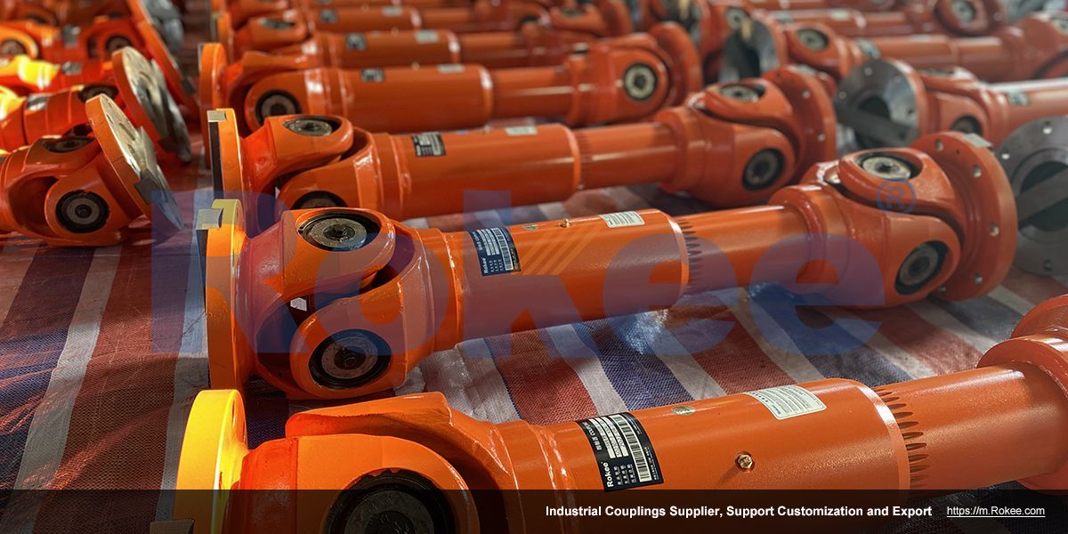
Universal Joint Couplings
Rokee is a chinese Universal Joint Couplings Manufacturer, provide Universal Joint Couplings processing and customization services, Over the years, with excellent quality, we have been continuously providing many coupling products of various categories and uses complying with multiple standards and a full range of services, from the Universal Joint Couplings selection to final installation and operation, for the industry fields of ferrous metallurgy, nuclear power, gas turbine, wind power, ropeway construction, lifting transportation, general equipment, etc. We strictly comply with quality system requirements and implement the whole process control to become a reliable and trustworthy partner of customers.
Providing customers with better Universal Joint Couplings is always our driving force. Our aim is to transmit power for you and generate value for both of us. We look forward to joining you and becoming your partner for common progress.
-
![SWC-BH Universal Joint Couplings,SWC-BH Cardan Shaft]()
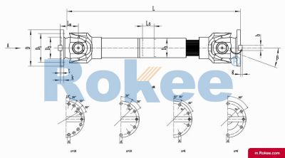
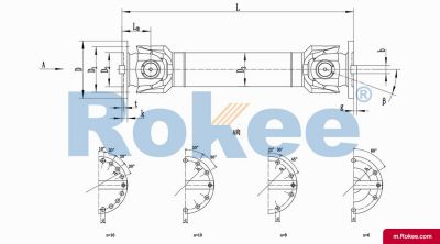
SWC-BH Cardan Shaft
SWC-BH standard telescopic welded universal joint couplingView More -
![SWC-CH Universal Joint Couplings,SWC-CH Cardan Shaft]()
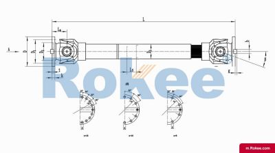
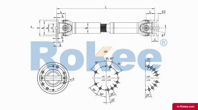
SWC-CH Cardan Shaft
SWC-CH long telescopic welded universal joint couplingView More -
![SWC-DH Universal Joint Couplings,SWC-DH Cardan Shaft]()
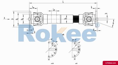
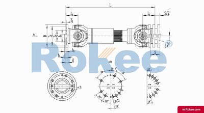
SWC-DH Cardan Shaft
SWC-DH short telescopic welded universal joint couplingView More -
![SWC-WD Universal Joint Couplings,SWC-WD Cardan Shaft]()
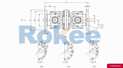
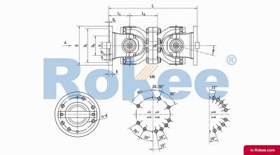
SWC-WD Cardan Shaft
SWC-WD non-telescopic short universal joint couplingView More -
![SWC-WH Universal Joint Couplings,SWC-WH Cardan Shaft]()
SWC-WH Cardan Shaft
SWC-WH non-telescopic welded universal joint couplingView More -
![SWP-A Universal Joint Couplings,SWP-A Cardan Shaft]()
SWP-A Cardan Shaft
SWP-A telescopic long type universal joint couplingView More -
![SWP-B Universal Joint Couplings,SWP-B Cardan Shaft]()
SWP-B Cardan Shaft
SWP-B telescopic short type universal joint couplingView More -
![SWP-C Universal Joint Couplings,SWP-C Cardan Shaft]()
SWP-C Cardan Shaft
SWP-C non telescopic short type universal joint couplingView More -
![SWP-D Universal Joint Couplings,SWP-D Cardan Shaft]()
SWP-D Cardan Shaft
SWP-D non telescopic long type universal joint couplingView More
Universal joint couplings, as a crucial mechanical transmission component, play an indispensable role in modern industrial equipment. It can connect shafts on different axes and allow for the transmission of power and motion with a certain degree of angular deviation between the shafts. From automotive drive systems to heavy industrial machinery, from aerospace to precision instruments, the presence of universal joint couplings can be seen everywhere.
Universal joint coupling is a mechanical device used to connect two rotating shafts with intersecting or frequently changing relative positions. Its core function is to achieve reliable power transmission in the presence of an angle between the shafts, while compensating for changes in shaft position caused by installation errors, working deformations, or thermal expansion. This unique performance makes universal joint couplings an ideal choice for solving complex transmission problems.
The fundamental difference between universal joint couplings and traditional couplings lies in their unique angular compensation capability. ordinary couplings usually require strict alignment of the two shafts, while universal joint couplings can operate normally with an angle of 5 ° -45 ° between the two shafts (the specific angle range depends on the structural type). This feature makes it particularly suitable for the following scenarios: connecting two axes that may change in spatial position; Compensate for shaft offset caused by manufacturing and installation errors, bearing deformation, or thermal expansion; Absorb vibrations and impacts in the transmission system.
According to different classification standards, universal joint couplings can be classified into various types. According to torsional elasticity, it can be divided into rigid universal joints (such as cross axis type) and flexible universal joints (such as rubber element type); According to speed characteristics, it can be divided into non constant velocity universal joints (such as ordinary cross shaft type), quasi constant velocity universal joints (such as double joint type), and constant velocity universal joints (such as cage type); According to the structural form, it can be divided into various types such as cross axis type, ball cage type, ball fork type, convex block type, three pin type, etc. Among them, the cross axle type is widely used due to its simple structure and convenient manufacturing, while the ball cage type is widely used in automotive drive axles due to its constant speed transmission characteristics.
Modern industry has put forward higher requirements for transmission systems, and universal joint couplings have also been continuously developed. Lightweight design uses high-strength alloys and composite materials to reduce weight while ensuring load-bearing capacity; Modular structure facilitates quick replacement and maintenance, reducing downtime; Intelligent monitoring technology integrates sensors to monitor the working status of couplings in real time, achieving predictive maintenance. These innovations enable universal joint couplings to adapt to more demanding working environments and more efficient transmission requirements.
The core function of a universal joint coupling is to transmit rotational motion and torque in the presence of an angle between the shafts, which is achieved through its sophisticated mechanical structure. A deep understanding of its working principle is crucial for the correct selection, use, and maintenance of universal joint couplings. From the most basic cross axis type to the complex ball cage type, different types of universal joint couplings, although having different structures, all follow the same kinematic principles.
The cross axis universal joint, as the most basic and widely used type, has a representative working principle. It mainly consists of two universal joint forks, a cross shaft, and four needle roller bearings. Two universal joint forks are respectively connected to the driving shaft and the driven shaft, and the four necks of the cross shaft are installed in the holes of the universal joint forks through needle roller bearings. When the driving shaft rotates, it drives the driven shaft to rotate through the cross shaft, and at the same time, the cross shaft can swing spatially within the universal joint fork to adapt to changes in the angle between the two shafts. However, this simple structure has an inherent characteristic - unequal velocity: when there is an angle between the two axes, the instantaneous angular velocity of the driven axis is not synchronized with the active axis, but fluctuates periodically, and the amplitude of the fluctuation increases with the increase of the angle. Theoretical analysis shows that the speed ratio relationship of a single cross axis universal joint follows the formula of 1- sin ² and 2- cos ² β (where 3 is the driving shaft angle, 3 is the driven shaft angle, and 3 is the two shaft angle). This inequality has little impact on low-speed heavy loads or small angle transmissions, but may cause vibration, noise, and additional loads in high-speed or large angle transmissions.
In order to overcome the problem of non-uniform transmission of single universal joints, double universal joint couplings have emerged. It is composed of two single universal joints connected by an intermediate shaft, and achieves constant speed transmission through clever design. There are three conditions for achieving constant speed transmission with dual universal joints: the angle between the intermediate shaft and the driving and driven shafts must be equal (β 1=β 2); The universal joint forks at both ends of the intermediate shaft must be located on the same plane; The axes of the driving shaft, driven shaft, and intermediate shaft should be coplanar. When these conditions are met, the non-uniform velocity effect caused by the first universal joint will be completely offset by the second universal joint, thereby enabling the driven shaft to achieve rotational motion completely synchronized with the driving shaft. In modern industrial applications, about 85% of cross axis universal joints are used in a dual form, especially in situations where smooth transmission is required such as automotive transmission shafts and steel mills.
The constant velocity universal joint represents a more advanced technological solution, which uses precise geometric design to ensure that the transmission point is always located on the bisector of the angle between the two axes, thereby achieving true constant velocity transmission. The cage type constant velocity universal joint is a typical representative, consisting of a star shaped sleeve (inner raceway), a spherical shell (outer raceway), steel balls, and a cage. Six steel balls run in six sets of tracks formed by the inner and outer raceways, and the cage keeps the steel balls in the same plane. This structure ensures that no matter how the angle between the two axes changes, the force transmitting steel ball is always located on the bisector of the angle, meeting the conditions of constant speed transmission. The cage type universal joint allows for a larger working angle (up to 47 °), and all steel balls participate in force transmission simultaneously, resulting in high load-bearing capacity and long service life. Therefore, it is widely used in the drive shaft of front wheel drive vehicles.
Motion compensation capability is another core characteristic of universal joint couplings. In addition to angular compensation (adapting to the angle between shafts), many universal joint couplings also have radial compensation (adapting to shaft offset) and axial compensation (adapting to changes in shaft distance) capabilities. For example, the telescopic ball cage universal joint allows for both angle changes and axial displacement through a special design of the inner and outer raceways, eliminating the need for traditional sliding splines and reducing friction losses. This composite compensation capability enables universal joint couplings to adapt to more complex working conditions, such as suspension motion during vehicle operation and thermal deformation of large equipment.
From a material perspective, modern universal joint couplings mainly use high-strength alloy steel (such as 20CrMnTi, 42CrMo, etc.), and key components undergo carburizing quenching or quenching and tempering heat treatment, with a surface hardness of HRC58-62 and good toughness at the core. The bearing components are mostly made of high-quality bearing steel (GCr15), matched with precision needle rollers or cylindrical rollers to ensure load-bearing capacity and service life. In recent years, engineering plastics and composite materials have also been applied in small universal joints and non heavy load situations, bringing advantages such as weight reduction and self-lubricating.
The cross axis universal joint is the most basic and widely used type, with a relatively simple structure mainly composed of two universal joint forks, a cross axis, and four sets of needle roller bearings. This type of coupling can be divided into various forms according to the structural changes of the bearing seat and cross head: SWC type integral fork head type, SWP type partial bearing seat type, SWZ type integral bearing seat type, etc. The biggest advantage of the cross axis type is its simple and compact structure, low manufacturing cost, easy maintenance, and ability to transmit large torque, making it particularly suitable for heavy machinery. For example, in metallurgical rolling mills, SWC type universal couplings can transmit up to 1000kN · m of torque and have an angle compensation capability of 10 ° -15 °. However, its limitations are also evident: when used in a single section, the transmission is not at the same speed, resulting in additional dynamic loads; The working angle is limited, generally not exceeding 20 degrees; Regular lubrication and maintenance are required. In practical applications, to overcome the problem of uneven speed, cross shaft universal couplings are usually used in pairs to form a double structure. The length of the intermediate shaft is determined according to actual needs, and constant speed transmission is achieved through reasonable arrangement.
The cage type constant velocity universal joint represents a higher level of technology, and its core structure includes a star sleeve, a spherical shell, steel balls, and a cage. According to whether it can expand and contract axially, it is divided into fixed type (RF section) and expandable type (VL section). The fixed ball cage joint allows a maximum axial angle of 47 °, and six steel balls participate in force transmission simultaneously. It has high load-bearing capacity and smooth transmission, and is widely used in car drive shafts. The telescopic ball cage joint has both angle compensation and axial displacement compensation capabilities, which can replace traditional sliding spline structures and reduce friction losses. The precision manufacturing requirements for cage type are high, and the inner and outer raceways need to be precision ground. The hardness usually reaches HRC60 or above, and the accuracy level of the steel ball is not lower than G10. The life test of a certain type of car's ball cage universal joint shows that its service life exceeds 300000 kilometers at a maximum angle of 25 ° and a speed of 2000rpm. The advantages of ball cage universal joints include: true constant speed transmission, no additional dynamic load; Large work perspective; High transmission efficiency (up to 98% -99%); Good sealing and maintenance free. However, relatively speaking, its structure is complex, the cost is high, and it is sensitive to foreign object invasion.
Ball fork universal joint is another type of constant velocity universal joint, which is divided into circular arc raceway type and straight groove raceway type. The circular raceway type consists of two universal joint forks and four transmission steel balls, with a simple structure that allows for a maximum shaft to shaft angle of 32 ° -33 °. It has been widely used in light vehicles. But its contact stress is high, and only some steel balls transmit force, resulting in relatively low load-bearing capacity and service life. The straight groove raceway type achieves constant speed transmission by machining straight grooves on two ball forks, so that the four steel balls are always located on the bisector of the angle between the two axes, allowing a maximum angle of 20 ° and a small amount of axial displacement. It is suitable for open type drive axles. The current application status of ball fork universal joints is gradually being replaced by cage type joints with better performance, but they are still used in some low-cost and light load situations.
The three pin universal joint is a quasi constant velocity universal joint consisting of two eccentric shaft forks and two three pin shafts, allowing for a large angle of intersection between adjacent shafts (up to 45 °). This structure is particularly suitable for situations that require large angle transmission, such as heavy-duty vehicle steering drive axles, which can provide the vehicle with a smaller turning radius and improve maneuverability. A certain type of mining dump truck adopts a three pin universal joint, which can reliably transmit a torque of 280kN · m even at a turning angle of 40 °. But its disadvantage is that it has a large radial size, takes up more space, and its transmission smoothness is not as good as that of a cage type.
The dual universal joint is essentially a quasi constant velocity universal joint composed of two compact cross axis universal joints. By reducing the length of the middle transmission shaft to the minimum, a structure similar to a double cross axis is formed. Its unique advantage is that it allows for larger inter axis angles (up to 50 °) and does not require specialized indexing mechanisms, making the structure relatively simple and reliable. Widely used in agricultural machinery and engineering vehicles, for example, the cutting head drive system of a certain type of combine harvester adopts a double universal joint, which performs well under frequent angle changing conditions.
Flexible universal couplings use elastic components such as rubber and polyurethane to replace traditional metal hinge structures, and compensate for shaft system deviations through the elastic deformation of the materials. The outstanding feature of this type of coupling is that it can buffer and reduce vibration, absorb impact, compensate for small deviations (generally not exceeding 3 °), and does not require lubrication. It is commonly used in small and medium power transmission systems. For example, rubber block universal couplings are commonly used in ship propulsion systems to compensate for installation errors and hull deformations, while isolating engine vibrations. But its load-bearing capacity is low, and the elastic components have aging problems, with a service life of usually 3-5 years.
In the intricate network of mechanical power transmission systems, the universal joint coupling stands as a fundamental and indispensable component, enabling the seamless transfer of torque between shafts that are not perfectly aligned. Often referred to simply as a U-joint, this mechanical device has evolved over centuries to become a cornerstone of modern engineering, finding applications in industries ranging from automotive and aerospace to manufacturing and agriculture. Its ability to accommodate angular misalignment, compensate for axial displacement, and transmit high levels of torque while maintaining relative simplicity in design makes it a versatile solution for countless mechanical challenges.
At its most basic level, a universal joint coupling operates on the principle of transferring rotational motion and torque between two shafts that intersect at an angle, allowing for relative movement without compromising power transmission. The fundamental structure of a typical U-joint consists of three key components: two yokes, each attached to one of the shafts being connected, and a cross-shaped central element known as a spider or cross-pin that links the two yokes together. Each arm of the cross-pin is fitted with bearings, which are housed within the ends of the yokes, enabling smooth rotation and swiveling movement. This configuration allows the yokes to pivot relative to each other around the cross-pin, accommodating changes in the angle between the two shafts while ensuring that torque is efficiently transmitted from the input shaft to the output shaft. When torque is applied to one shaft, it is transferred through the yoke to the cross-pin, which then distributes the rotational force to the second yoke and ultimately to the output shaft. The bearings within the yoke ends play a critical role in reducing friction during this process, minimizing wear and ensuring the smooth operation of the joint even under varying angular conditions.
However, it is important to note that the basic single universal joint coupling exhibits a characteristic limitation known as angular velocity fluctuation. When the two shafts are aligned at an angle greater than zero, the angular velocity of the output shaft is not constant relative to the input shaft, but rather fluctuates cyclically during each rotation. This fluctuation occurs because the effective radius at which the torque is applied changes as the cross-pin rotates within the yokes. The magnitude of this velocity variation increases with the angle of misalignment between the shafts, potentially leading to vibration, noise, and increased wear on other components of the transmission system. To address this issue, engineers have developed the double universal joint coupling, which consists of two single U-joints connected by an intermediate shaft. When properly aligned, the velocity fluctuations from the first joint are canceled out by the second joint, resulting in a constant angular velocity at the output shaft. This configuration is particularly useful in applications where long shaft distances or significant angular misalignments are present, such as in heavy-duty trucks, industrial machinery, and automotive drivetrains.
Another specialized variation of the universal joint coupling is the constant velocity (CV) joint, which is designed to eliminate angular velocity fluctuation entirely, even at large angles of misalignment. Unlike the basic U-joint, which relies on a cross-pin and yoke configuration, CV joints use a more complex arrangement of balls or rollers within a grooved housing to maintain a constant velocity ratio between the input and output shafts. This makes them ideal for applications where smooth power transmission is critical, such as in front-wheel drive vehicles, where the drive shafts must accommodate both the rotational motion of the engine and the vertical and angular movements of the suspension system. While CV joints offer superior performance in terms of velocity stability, they are generally more complex and costly to manufacture than traditional U-joints, making them less suitable for applications where cost and simplicity are primary considerations.
The materials used in the construction of universal joint couplings are carefully selected based on the specific requirements of the application, including the level of torque to be transmitted, the operating environment, and the expected service life. For most standard applications, the yokes and cross-pin are typically made from high-strength steel alloys, such as 20CrMnTi, which undergo heat treatment processes like carburizing and quenching to achieve a hard surface and a tough core. This combination of properties ensures that the components can withstand high levels of stress and wear while remaining resistant to fatigue failure. The bearings within the yoke ends are usually made from hardened steel with precision-ground surfaces to minimize friction and ensure smooth operation. In applications where corrosion resistance is a concern, such as marine or offshore environments, components may be made from stainless steel or coated with protective materials like zinc or chrome. For light-duty applications with lower torque requirements, plastic or aluminum components may be used to reduce weight and cost, although these materials are not suitable for heavy-duty industrial use.
The versatility of universal joint couplings is reflected in their wide range of applications across numerous industries. In the automotive industry, they are a critical component of drivetrain systems, connecting the transmission to the drive axle in rear-wheel drive vehicles and serving as part of the half-shaft assemblies in four-wheel drive and all-wheel drive vehicles. They also find use in steering systems, where they allow for the transfer of rotational motion from the steering wheel to the steering gear, accommodating the angular misalignments between the various components of the steering column. In industrial machinery, universal joint couplings are used in a variety of equipment, including conveyor systems, pumps, compressors, and electric motors, where they enable the connection of shafts that may not be perfectly aligned due to manufacturing tolerances or structural movement. Heavy-duty industrial applications, such as metallurgical machinery, rolling mills, and construction equipment, require robust U-joint designs capable of transmitting extremely high torques, often using double joint configurations with reinforced yokes and large-diameter cross-pins.
The agricultural industry also relies heavily on universal joint couplings for power transmission in equipment such as tractors, harvesters, and irrigation systems. In these applications, the U-joints must be able to withstand harsh operating conditions, including exposure to dust, dirt, moisture, and extreme temperatures, while transmitting power between the tractor's engine and various implements. The ability to accommodate angular misalignment is particularly important in agricultural machinery, as the implements often move relative to the tractor during operation. In the aerospace industry, universal joint couplings are used in aircraft control systems, where they enable the transfer of motion from the cockpit controls to the various flight surfaces, such as the ailerons, elevators, and rudder. These aerospace-grade U-joints are manufactured to extremely tight tolerances and are made from lightweight, high-strength materials to meet the strict performance and safety requirements of the aviation industry.
Proper maintenance is essential to ensure the reliable operation and extended service life of universal joint couplings. One of the most critical maintenance tasks is regular lubrication, as the bearings and moving parts of the joint rely on a continuous supply of lubricant to minimize friction and wear. The type of lubricant used depends on the operating conditions, with high-temperature applications requiring synthetic lubricants that can withstand elevated temperatures without breaking down. In general, a high-viscosity grease with good anti-wear and anti-corrosion properties, such as NLGI 2 grade grease, is recommended for most standard applications. Lubrication should be performed at regular intervals, typically every 500 hours of operation or every three months, with the exact frequency depending on the operating environment and the manufacturer's recommendations. It is also important to ensure that the lubricant is applied correctly, filling the cavity of the joint to approximately one-third to one-half of its volume to avoid over-lubrication, which can lead to increased friction and overheating.
Regular inspection is another key aspect of U-joint maintenance. Visual inspections should be performed periodically to check for signs of wear, damage, or corrosion, including cracks in the yokes or cross-pin, excessive play in the bearings, and leakage of lubricant. Excessive play in the joint, which is often indicated by a clicking or clunking sound during operation, is a sign that the bearings or cross-pin are worn and need to be replaced. Vibration or noise during operation can also indicate misalignment, unbalanced shafts, or worn components. In such cases, the joint should be inspected and the necessary adjustments or repairs made to prevent further damage to the coupling or other parts of the transmission system. For high-speed applications, regular balancing of the shafts and U-joint assembly is important to minimize vibration and ensure smooth operation. This can be achieved using specialized equipment to measure and correct any imbalance in the rotating components.
Proper installation is also critical to the performance and service life of universal joint couplings. During installation, it is essential to ensure that the two shafts are aligned within the recommended angular limits, which typically range from 5 degrees to 45 degrees depending on the type of joint and the application. Exceeding these limits can lead to increased wear, vibration, and premature failure of the joint. The use of laser alignment tools can help to achieve precise alignment, ensuring that the angular and axial deviations between the shafts are within acceptable limits. It is also important to ensure that the bolts used to attach the yokes to the shafts are tightened to the correct torque specification using a torque wrench, following a diagonal tightening sequence to ensure even pressure distribution. Loose bolts can lead to excessive vibration and wear, while over-tightened bolts can cause damage to the shaft or yoke.
Despite their robustness and reliability, universal joint couplings can experience a variety of problems during their service life, most of which are related to wear, misalignment, or inadequate maintenance. One of the most common issues is bearing wear, which can occur due to insufficient lubrication, contamination of the lubricant with dust or moisture, or overloading of the joint. Worn bearings can lead to excessive play in the joint, increased vibration, and eventually, failure of the cross-pin or yokes. Another common problem is cross-pin failure, which is often caused by fatigue due to repeated stress, overloading, or manufacturing defects. Cross-pin failure can result in a sudden loss of power transmission, which can be catastrophic in critical applications such as automotive or aerospace systems. Lubrication failure, which can occur due to leaking seals, incorrect lubricant selection, or failure to lubricate at regular intervals, can lead to increased friction, overheating, and premature wear of the joint components.
To address these issues, a number of troubleshooting and repair strategies can be employed. In the case of worn bearings, the solution typically involves replacing the bearings and seals, cleaning the joint components, and refilling with the correct lubricant. If the yokes or cross-pin are damaged or worn beyond repair, they must be replaced with new components that match the original specifications. For problems related to misalignment, the shafts should be realigned using precision tools to ensure that the angular and axial deviations are within the recommended limits. In some cases, the use of adjustable mounting brackets or shims may be necessary to achieve the correct alignment. To prevent lubrication failure, it is important to use high-quality seals to prevent contamination, select the appropriate lubricant for the operating conditions, and establish a regular lubrication schedule. In high-demand applications, automatic lubrication systems can be installed to ensure a continuous supply of lubricant, reducing the risk of human error and improving the reliability of the joint.
Looking to the future, the development of universal joint couplings is likely to be driven by advancements in materials science, manufacturing technology, and the increasing demand for more efficient and reliable power transmission systems. One area of ongoing research is the development of new materials with improved properties, such as higher strength-to-weight ratios, better corrosion resistance, and increased wear resistance. The use of composite materials, such as carbon fiber-reinforced polymers, may offer opportunities to reduce the weight of U-joint components while maintaining or improving their strength, making them ideal for aerospace and automotive applications where weight reduction is a key objective. Advancements in manufacturing technology, such as additive manufacturing (3D printing), are also likely to have a significant impact on the production of universal joint couplings. 3D printing allows for the creation of complex geometries that are difficult or impossible to achieve with traditional manufacturing methods, enabling the design of U-joints with improved performance characteristics, such as enhanced load distribution and reduced weight. It also offers the potential for on-demand manufacturing, reducing lead times and inventory costs.
Another trend in the development of universal joint couplings is the integration of smart technology, such as sensors and monitoring systems, to enable predictive maintenance. By embedding sensors within the joint components, it is possible to monitor key parameters such as temperature, vibration, and wear in real-time, providing early warning of potential failures before they occur. This allows for maintenance to be performed proactively, reducing the risk of unplanned downtime and improving the overall reliability of the transmission system. In addition, the use of data analytics and machine learning algorithms can help to optimize maintenance schedules based on actual operating conditions, further improving the efficiency and cost-effectiveness of maintenance programs.
In conclusion, the universal joint coupling is a versatile and essential component of modern mechanical power transmission systems, enabling the seamless transfer of torque between misaligned shafts across a wide range of industries. Its simple yet effective design, combined with its ability to accommodate angular misalignment and transmit high levels of torque, has made it a staple of engineering applications for over a century. From automotive drivetrains to industrial machinery and aerospace control systems, U-joints play a critical role in ensuring the reliable and efficient operation of countless pieces of equipment. Proper maintenance, including regular lubrication and inspection, is essential to maximize the service life of these components and prevent premature failure. As technology continues to advance, the future of universal joint couplings looks promising, with ongoing developments in materials, manufacturing, and smart monitoring systems set to further improve their performance, reliability, and efficiency. Whether in traditional applications or emerging technologies, the universal joint coupling will continue to be a vital part of the mechanical systems that power our world.
« Universal Joint Couplings » Update Date: 2026/1/10
URL: https://m.rokee.com/tags/universal-joint-couplings.html