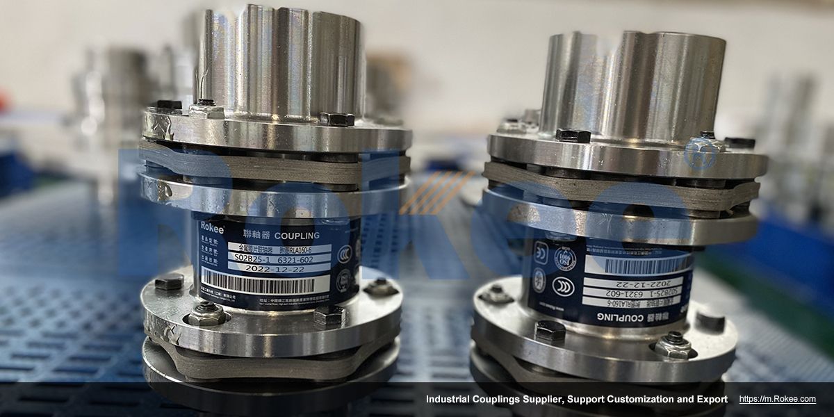
RLAT Super Long Wheelbase Metal Diaphragm Coupling
Adopting an intermediate shaft design, suitable for ultra long shaft spacing power transmission applications.
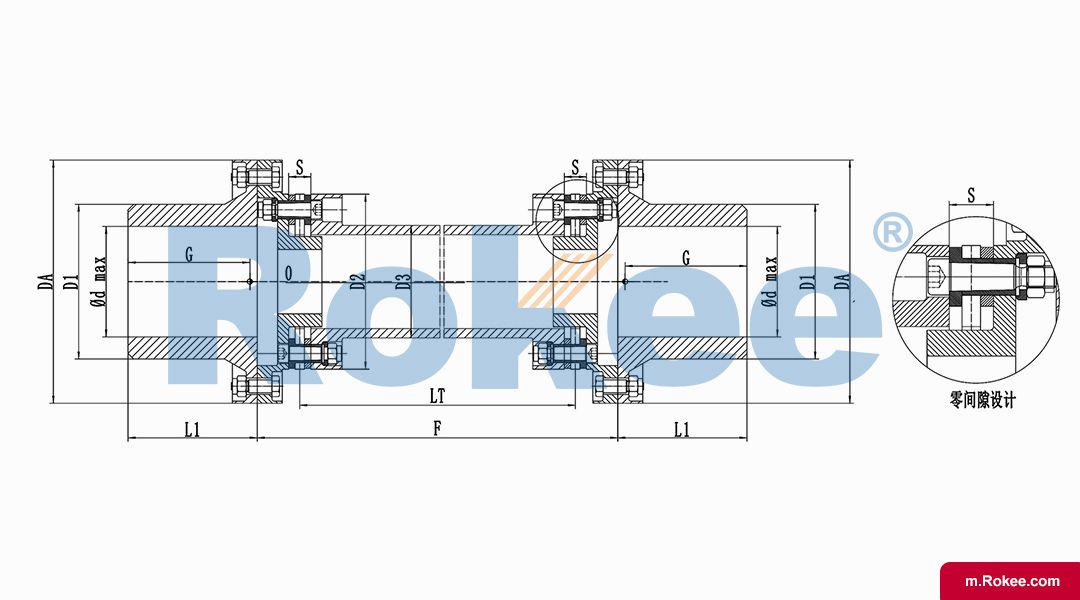
| Model | DA | D1 | D2 | D3 | d1(max) | L1 | LT | LS Design calculation according to 457.2(18") | Maximum Allowable Speed | Nominal Torque | Maximum Instantaneous Torque |
|---|---|---|---|---|---|---|---|---|---|---|---|
| (mm) | (mm) | (mm) | (mm) | (mm) | (mm) | (mm) | (mm) | n max(r/min) | T(N.m) | Tmax(N.m) | |
| RLAT95-6 | 132 | 84 | 95 | 56 | 60 | 70 | =LS-46 | Provide data according to design requirements | 28900 | 1000 | 1300 |
| RLAT125-6 | 158 | 105 | 125 | 72 | 75 | 90 | =LS-55 | 24200 | 2300 | 3000 | |
| RLAT145-6 | 182 | 133 | 145 | 87 | 95 | 110 | =LS-65 | 21000 | 4000 | 5000 | |
| RLAT175-6 | 220 | 161 | 175 | 109 | 115 | 135 | =LS-77 | 17400 | 6700 | 8500 | |
| RLAT205-6 | 249 | 189 | 205 | 125 | 135 | 150 | =LS-83 | 15300 | 10500 | 13000 | |
| RLAT220-6 | 266 | 210 | 220 | 140 | 150 | 175 | =LS-95 | 14400 | 14500 | 18500 | |
| RLAT250-6 | 295 | 231 | 250 | 162 | 165 | 200 | =LS-112 | 12900 | 21000 | 27000 | |
| RLAT270-6 | 328 | 252 | 270 | 171 | 180 | 210 | =LS-119 | 11600 | 26500 | 35000 | |
| RLAT295-6 | 355 | 280 | 295 | 187 | 200 | 230 | =LS-131 | 10800 | 35000 | 45500 | |
| RLAT320-6 | 382 | 301 | 320 | 201 | 215 | 250 | =LS-138 | 10000 | 41000 | 52000 | |
| Model | Mass Point G | Angular Deviation | Maximum axial deviation | L2 | Intermediate Mass m | Intermediate moment of inertia | Intermediate torsional stiffness | Weight M | Torsional Stiffness | Rotational Inertia | Total Mass (KG) |
| (mm) | (±△º) | (Max±△mm) | (mm) | 10-3kg/mm | Js10-6(Kg.m²/mm) | Ct-106(Nm.mm/rad) | (Kg) | Ct-106(N.m/rad) | J(Kg.m²) | ||
| RLAT95-6 | 66 | 0.35 | 1.6 | - | 3.92 | 2.76 | 28.2 | 8.4 | 0.05 | 0.014 | (3.92/1000)*(Ls-457.2)+8.4 |
| RLAT125-6 | 81 | 2 | - | 5.91 | 6.95 | 70.9 | 14.4 | 0.118 | 0.036 | (5.91/1000)*(Ls-457.2)+14.4 | |
| RLAT145-6 | 93.5 | 2.4 | - | 8.19 | 14.1 | 144 | 23.6 | 0.229 | 0.084 | (8.19/1000)*(Ls-457.2)+23.6 | |
| RLAT175-6 | 111 | 3 | - | 11.6 | 31.7 | 323 | 40.12 | 0.468 | 0.216 | (11.6/1000)*(Ls-457.2)+40.12 | |
| RLAT205-6 | 121.5 | 3.8 | - | 16.2 | 58 | 591 | 59 | 0.806 | 0.416 | (16.2/1000)*(Ls-457.2)+59 | |
| RLAT220-6 | 137 | 4 | - | 19.8 | 89.2 | 909 | 79.2 | 1.17 | 0.671 | (19.8/1000)*(Ls-457.2)+79.2 | |
| RLAT250-6 | 155.5 | 4.6 | - | 23.1 | 141 | 1433 | 107 | 1.76 | 1.13 | (23.1/1000)*(Ls-457.2)+107 | |
| RLAT270-6 | 166 | 5 | - | 28.3 | 191 | 1944 | 140 | 2.34 | 1.789 | (28.3/1000)*(Ls-457.2)+140 | |
| RLAT295-6 | 179 | 5.6 | - | 35.3 | 283 | 2889 | 182 | 3.25 | 2.8 | (35.3/1000)*(Ls-457.2)+182 | |
| RLAT320-6 | 191.5 | 5.8 | - | 38.1 | 355 | 3620 | 224 | 4.09 | 4.01 | (38.1/1000)*(Ls-457.2)+224 |
| Model | D | D1 | D2 | D3 | d1(max) | L1 | LT | LS Design calculation according to 457.2(18") | Maximum Allowable Speed | Nominal Torque | Maximum Instantaneous Torque |
|---|---|---|---|---|---|---|---|---|---|---|---|
| (mm) | (mm) | (mm) | (mm) | (mm) | (mm) | (mm) | (mm) | n max(r/min) | T(N.m) | Tmax(N.m) | |
| RLAT145-8 | 182 | 133 | 145 | 87 | 95 | 110 | =LS-65 | Provide data according to design requirements | 21000 | 5700 | 7400 |
| RLAT175-8 | 220 | 161 | 175 | 109 | 115 | 135 | =LS-77 | 17400 | 9600 | 12300 | |
| RLAT205-8 | 249 | 189 | 205 | 125 | 135 | 150 | =LS-83 | 15300 | 15000 | 19000 | |
| RLAT220-8 | 266 | 210 | 220 | 140 | 150 | 175 | =LS-95 | 14400 | 20000 | 26500 | |
| RLAT250-8 | 295 | 231 | 250 | 162 | 165 | 200 | =LS-112 | 12900 | 29200 | 38200 | |
| RLAT270-8 | 328 | 252 | 270 | 171 | 180 | 210 | =LS-119 | 11600 | 38100 | 49000 | |
| RLAT295-8 | 355 | 280 | 295 | 187 | 200 | 230 | =LS-131 | 10800 | 49500 | 64000 | |
| RLAT320-8 | 382 | 301 | 320 | 201 | 215 | 250 | =LS-138 | 10000 | 59000 | 77000 | |
| RLAT350-8 | 410 | 322 | 350 | 218 | 230 | 270 | =LS-148 | 9300 | 81000 | 105000 | |
| RLAT390-8 | 462 | 364 | 390 | 248 | 260 | 310 | =LS-169 | 8300 | 115000 | 150000 | |
| RLAT435-8 | 510 | 413 | 435 | 280 | 295 | 340 | =LS-191 | 7500 | 168500 | 220000 | |
| RLAT498-8 | 580 | 469 | 498 | 324 | 335 | 390 | =LS-213 | 6600 | 250000 | 320000 | |
| RLAT545-8 | 625 | 511 | 545 | 355 | 365 | 425 | =LS-233 | 6100 | 330000 | 420000 | |
| RLAT595-8 | 680 | 553 | 595 | 387 | 395 | 460 | =LS-248 | 5600 | 410000 | 540000 | |
| Model | Mass Point G | Angular Deviation | Maximum axial deviation | L2 | Intermediate Mass m | Intermediate moment of inertia | Intermediate torsional stiffness | Weight M | Torsional Stiffness | Rotational Inertia | Total Mass (KG) |
| (mm) | (±△º) | (Max±△mm) | (mm) | 10-3kg/mm | Js10-6(Kg.m²/mm) | Ct-106(Nm.mm/rad) | (Kg) | Ct-106(N.m/rad) | J(Kg.m²) | ||
| RLAT145-8 | 94 | 0.25 | 1.6 | - | 8.19 | 14.1 | 144 | 23.9 | 0.273 | 0.085 | (8.19/1000)*(LS-457.2)+23.9 |
| RLAT175-8 | 111.5 | 1.8 | - | 11.6 | 31.7 | 323 | 40.5 | 0.578 | 0.216 | (11.6/1000)*(LS-457.2)+40.5 | |
| RLAT205-8 | 122 | 2.4 | - | 16.2 | 58 | 591 | 59.4 | 1.019 | 0.42 | (16.2/1000)*(LS-457.2)+59.4 | |
| RLAT220-8 | 138 | 2.6 | - | 19.8 | 89.2 | 909 | 80 | 1.51 | 0.678 | (19.8/1000)*(LS-457.2)+80 | |
| RLAT250-8 | 156.5 | 3 | - | 23.1 | 141 | 1433 | 108 | 2.33 | 1.14 | (23.1/1000)*(LS-457.2)+108 | |
| RLAT270-8 | 166.5 | 3.2 | - | 28.3 | 191 | 1944 | 141 | 3.12 | 1.8 | (28.3/1000)*(LS-457.2)+141 | |
| RLAT295-8 | 180 | 2.6 | - | 36.3 | 283 | 2889 | 184 | 4.44 | 2.83 | (36.3/1000)*(LS-457.2)+184 | |
| RLAT320-8 | 193 | 3.8 | - | 38.1 | 365 | 3620 | 227 | 5.61 | 4.06 | (38.1/1000)*(LS-457.2)+227 | |
| RLAT350-8 | 69 | 3.8 | - | 48.8 | 532 | 5422 | 283 | 7.98 | 5.82 | (48.8/1000)*(LS-457.2)+283 | |
| RLAT390-8 | 78.5 | 4.4 | - | 58.7 | 833 | 8485 | 406 | 12.2 | 10.7 | (58.7/1000)*(LS-457.2)+406 | |
| RLAT435-8 | 88 | 5 | - | 79.3 | 1427 | 14542 | 566 | 19.7 | 18.9 | (79.3/1000)*(LS-457.2)+566 | |
| RLAT498-8 | 99 | 5.8 | - | 99.7 | 2415 | 24613 | 828 | 32 | 36 | (99.7/1000)*(LS-457.2)+828 | |
| RLAT545-8 | 109 | 6.4 | - | 122 | 3536 | 36032 | 1055 | 43.7 | 54.2 | (122/1000)*(LS-457.2)+1055 | |
| RLAT595-8 | 116.5 | 7.2 | - | 138 | 4769 | 48597 | 1331 | 58.5 | 80.5 | (138/1000)*(LS-457.2)+1331 |
| Model | D | D1 | D2 | D3 | d1(max) | L1 | LT | LS Design calculation according to 457.2(18") | Maximum Allowable Speed | Nominal Torque | Maximum Instantaneous Torque |
|---|---|---|---|---|---|---|---|---|---|---|---|
| (mm) | (mm) | (mm) | (mm) | (mm) | (mm) | (mm) | (mm) | n max(r/min) | T(N.m) | Tmax(N.m) | |
| RLAT220-10 | 266 | 210 | 220 | 140 | 150 | 175 | =LS-95 | Provide data according to design requirements | 14400 | 26800 | 34800 |
| RLAT250-10 | 295 | 231 | 250 | 162 | 165 | 200 | =LS-112 | 12900 | 38300 | 49800 | |
| RLAT270-10 | 328 | 252 | 270 | 171 | 180 | 210 | =LS-119 | 11600 | 49400 | 64200 | |
| RLAT295-10 | 355 | 280 | 295 | 187 | 200 | 230 | =LS-131 | 10800 | 64000 | 83200 | |
| RLAT320-10 | 382 | 301 | 320 | 201 | 215 | 250 | =LS-138 | 10000 | 76500 | 99500 | |
| RLAT350-10 | 410 | 322 | 350 | 218 | 230 | 270 | =LS-148 | 9300 | 105100 | 136600 | |
| RLAT390-10 | 462 | 364 | 390 | 248 | 260 | 310 | =LS-169 | 8300 | 151800 | 197300 | |
| RLAT435-10 | 510 | 413 | 435 | 280 | 295 | 340 | =LS-191 | 7500 | 219600 | 285500 | |
| RLAT498-10 | 580 | 469 | 498 | 324 | 335 | 390 | =LS-213 | 6600 | 321800 | 422200 | |
| RLAT545-10 | 625 | 511 | 545 | 355 | 365 | 425 | =LS-233 | 6100 | 430000 | 559000 | |
| RLAT595-10 | 680 | 553 | 595 | 387 | 395 | 460 | =LS-248 | 5600 | 535000 | 695500 | |
| Model | Mass Point G | Angular Deviation | Maximum axial deviation | L2 | Intermediate Mass m | Intermediate moment of inertia | Intermediate torsional stiffness | Weight M | Torsional Stiffness | Rotational Inertia | Total Mass (KG) |
| (mm) | (±△º) | (Max±△mm) | (mm) | 10-3kg/mm | Js10-6(Kg.m²/mm) | Cts-106(Nm.mm/rad) | (Kg) | Ct-106(N.m/rad) | J(Kg.m²) | ||
| RLAT220-10 | 139 | 0.15 | 1.6 | - | 19.8 | 89.2 | 909 | 80.6 | 1.31 | 0.648 | (19.8/1000)*(LS-457.2)+80.6 |
| RLAT250-10 | 157.5 | 2 | - | 23.1 | 141 | 1433 | 109 | 2.02 | 1.15 | (23.1/1000)*(LS-457.2)+109 | |
| RLAT270-10 | 167.5 | 2.1 | - | 28.3 | 191 | 1944 | 142 | 2.73 | 1.82 | (28.3/1000)*(LS-457.2)+142 | |
| RLAT295-10 | 191 | 2.4 | - | 35.5 | 283 | 2889 | 186 | 3.77 | 2.86 | (35.5/1000)*(LS-457.2)+186 | |
| RLAT320-10 | 194 | 2.4 | - | 38.1 | 353 | 3620 | 229 | 4.71 | 4.11 | (38.1/1000)*(LS-457.2)+229 | |
| RLAT350-10 | 211 | 2.4 | - | 48.8 | 532 | 5422 | 286 | 6.78 | 5.88 | (48.8/1000)*(LS-457.2)+286 | |
| RLAT390-10 | 239 | 2.8 | - | 58.7 | 833 | 8485 | 409 | 10.2 | 10.8 | (58.7/1000)*(LS-457.2)+409 | |
| RLAT435-10 | 262 | 3.2 | - | 79.3 | 1427 | 14542 | 572 | 15.8 | 19.1 | (79.3/1000)*(LS-457.2)+572 | |
| RLAT498-10 | 297.5 | 3.8 | - | 99.7 | 2415 | 24613 | 836 | 24.7 | 36.4 | (99.7/1000)*(LS-457.2)+836 | |
| RLAT545-10 | 322 | 4 | - | 122 | 3536 | 36032 | 1065 | 33.8 | 54.7 | (122/1000)*(LS-457.2)+1065 | |
| RLAT595-10 | 346.5 | 4.6 | - | 138 | 4769 | 48597 | 1342 | 43.5 | 81.2 | (138/1000)*(LS-457.2)+1342 |
The ultra long wheelbase diaphragm coupling is mainly composed of two half couplings, a middle diaphragm group, and connecting bolts. Its core lies in the intermediate membrane group, which is usually made of high-strength and high elastic alloy materials, with excellent fatigue resistance and corrosion resistance. The diaphragm is formed into a specific corrugated shape through precision machining and heat treatment processes, allowing the coupling to absorb radial, axial, and angular displacements between shaft systems while transmitting torque, effectively reducing vibration and noise.
The design of ultra long wheelbase is achieved by increasing the number of diaphragm groups and adjusting the arrangement of diaphragms. This design not only increases the load-bearing capacity of the coupling, but also enables it to adapt to a wider range of shaft spacing changes, thereby meeting the needs of complex transmission systems.
Performance advantages
High load-bearing capacity: Thanks to the special structure and material selection of the diaphragm group, the ultra long wheelbase Plate coupling can withstand large torque and axial force, ensuring the stable operation of the transmission system.
Good compensation performance: The elastic deformation ability of the diaphragm group enables the coupling to compensate for various displacements between shaft systems, including radial, axial, and angular displacements, effectively reducing vibration and noise caused by installation errors, thermal expansion, and other factors.
High precision transmission: Due to the good balance of rigidity and elasticity of the diaphragm group, the ultra long wheelbase diaphragm coupling can maintain high transmission accuracy, ensuring the stability and reliability of the transmission system.
Easy to install and maintain: The Shim Pack coupling has a compact structure, light weight, and is easy to disassemble and reassemble, reducing the cost and time of installation and maintenance.
Ultra long wheelbase Steel Laminae couplings are widely used in various industrial fields that require long-distance transmission, such as wind power generation, shipbuilding, heavy machinery, petrochemicals, etc. Especially in the field of wind power generation, as the length of wind turbine blades continues to increase, the distance between shaft systems also increases. The ultra long wheelbase Flexible Membrane coupling has become an ideal choice for connecting the main shaft of the wind turbine and the generator shaft due to its excellent compensation performance and load-bearing capacity.
URL: https://m.rokee.com/diaphragm-couplings/rlat-super-long-wheelbase-metal-diaphragm-coupling.html