Design Of Drum Gear Coupling
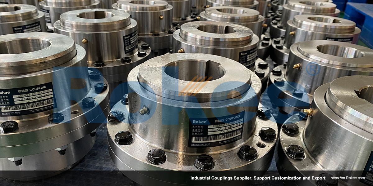
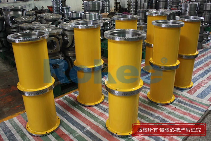
The drum gear coupling is mainly composed of an inner gear ring, an outer gear shaft sleeve, an end cover, a sealing device, and other parts. Its key feature is that the tooth tip of the outer gear shaft sleeve is made into a drum shape, and the tooth surface is in a circular arc shape. This design enables the coupling to adapt to displacement compensation at certain angles, radial and axial directions, thereby maintaining stable transmission performance.
Design points
Formation of drum shaped teeth:
The inner gear sleeve is a regular straight tooth internal gear, while the outer gear sleeve is a drum shaped tooth, often processed by hobbing.
The trajectory of the rolling cutter center is a circular arc with a certain point as the center and R as the radius, where R is the radius of the displacement circle. Generally, R=(0.5~1.9) d, where d is the diameter of the dividing circle. The value of R will affect the allowable angular displacement and contact strength of the coupling.Tooth profile curvature radius:
The curvature radius of the tooth profile of the drum shaped teeth on the meshing plane and the working circular section needs to be accurately calculated to ensure the smoothness and load-bearing capacity of the meshing.
To simplify the calculation, arcs with radii Re and Rt can be used instead of the actual hyperbolic tooth profile, and the error is acceptable within the scope of engineering calculations.Side clearance design:
When the internal and external teeth of the drum toothed coupling mesh, there must be sufficient backlash on the non meshing side to compensate for machining errors, angular displacement, and assembly errors between the shaft sleeve and the shaft.
There are various methods for determining backlash, such as calculating the common normal line of the external gear based on the mesh without backlash and giving a negative deviation, or using different displacement coefficients to change the tooth thickness and cause backlash.Geometric calculation:
Calculation of geometric parameters including pitch circle diameter, number of teeth, modulus, tooth profile angle, tooth crest height coefficient, tooth root height coefficient, tooth width, etc.
The selection of these parameters needs to be comprehensively considered based on factors such as the operating conditions of the coupling, the magnitude of the transmitted torque, the allowable angular displacement, and radial displacement.
Performance characteristics and optimization
High torque transmission capability:
The tooth profile design of the crown gear coupling is reasonable, with a large tooth contact area and the ability to withstand large torque, making it suitable for heavy-duty transmission applications.Displacement compensation capability:
Due to the presence of drum shaped teeth, the coupling can adapt to displacement compensation at certain angles, radial and axial directions, making the transmission more stable and reliable.Optimization suggestions:
In design, the bearing capacity and service life of the coupling can be improved by optimizing the drum curve, selecting appropriate number and modulus of teeth, improving tooth surface hardness and lubrication conditions, and other measures.
Material selection and manufacturing process
Material selection:
The inner gear ring and outer gear shaft sleeve are usually made of high-strength, wear-resistant, and corrosion-resistant materials, such as alloy steel, stainless steel, etc.
The selection of materials such as end caps and sealing devices also needs to consider their strength and sealing performance.Manufacturing process:
The machining of drum shaped teeth usually adopts precision machining methods such as hobbing or gear hobbing to ensure the accuracy and surface quality of the tooth profile.
The assembly and debugging process of the coupling also requires strict quality control to ensure its transmission performance and reliability.
Drum gear couplings are widely used in various mechanical transmission systems, especially in situations where heavy loads need to be borne and there are requirements for compensating for large angular and radial displacements. With the continuous development of the mechanical industry, the performance requirements for drum gear couplings are also increasing. In the future, by continuously improving design methods and manufacturing processes, enhancing material performance and service life, drum gear couplings will be applied and developed in a wider range of fields.
« Design Of Drum Gear Coupling » Post Date: 2023/8/14
URL: https://m.rokee.com/blog/design-of-drum-gear-coupling.html
- Why Does The Drum Gear Coupling Move
- Working Condition Coefficient Of Drum Gear Coupling
- Working Condition Of Drum Gear Coupling
- Working Principle Of Drum Gear Coupling
- Worn Drum Gear Coupling
- Direct Production Plant For Drum Gear Couplings
- Dimensions Of Drum Gear Couplings
- Differences In Drum Gear Couplings
- Supply Of Drum Gear Coupling
- Wholesale Base For Drum Gear Couplings